| 1. Adaptive Clearing reduces roughing time and increases tool life. |
This is a simple machining. Let's machine from a recangular stock.

What Z-depth?
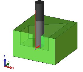
Too deep! Tool is broken.
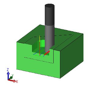
Maybe OK if stepover is samll....
If tool broken, where ?
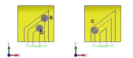
Tool may be broken at point a or b. How about point c ?
At acute angle point, cutting load is maximum.
What do you do when tool broken?
Are you decrease F(feed).?
How much do you decrease?
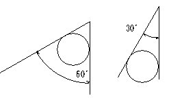
When the angle is 30 degrees, you decrease to half of when 60 degrees. Is it OK?
When 15 degrees, do you decrease to half of it?
It is not good maybe.
You must think of stock to leave
You have decided F(feed) and S(Spindle speed) suitably, haven't you?

Is it suitably that you decrease F and keep S unchanged ?
What can you do to use
 ?
?First, I talk about roughing operation without apaptive clearing.
The roughing operation is named 'Pocket Clearing'. You can use it for each of core and cavity shape .
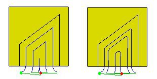
Can you see differnce between two?
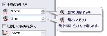
The left is with constant stepover.
The right is with variable stepover from 3 mm to 9.5 mm.
The variable stepover is suitable for high speed machining.
You can select constant or variable stepover with HSMWorks.
One more differnce. Look at acute corner.
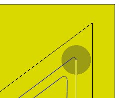
The model corner is acute and no R. But the path is rounded.
This rounding decreases cutting load at the corner.

I set minimum cutting radius R0.8.
If you want, you can set R0 and you can get acute angle path.
I have talked about smooth path. It is suitable for high speed machining.
It reduces cutting load at acute corner.
Adaptive Clearing
'Adaptive Clearing' is translated into Japanese as 'Fuka-seigyo' meaning controlling cutting load.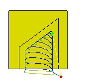
What is the differnce? See the following animation with attension to cutting load.
Cutting load is small at first, and increasing, and then keep constant, and decreasing at end.
This is 'Adaptive Clearing'. It controls cutting load.
Other system generates tool path in consider of only stepover, and not consider of load.
So Adaptive Clearing is innovation.
Next look at corner
This stepover is smaller, but cutting load is the same.
Please look at the followed three paths. Let's analyze load.
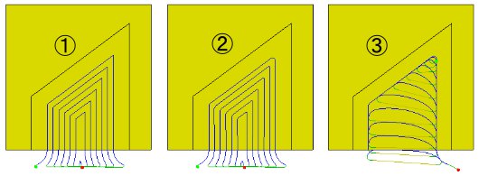
① Constant stepover. The path has acute corner.
② Variable stepover. It is suitable for high speed machining.
③ Adaptive Clearing.
I make graphs.
X-axis : length of move
Y-axis : stock volume removed per unit move
Y-axis : stock volume removed per unit move
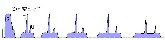
The following is graph of ①.
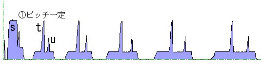
At point s, load is big.
Then at point t and u, there are spikes. And spikes repeats after them.
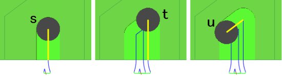
You can see the points s,t,u of the graph corresponds to s,t,u of the tool-moving image.
At first point s, load is big, because width of cut is the same as the tool diameter.
At point t, load is about the same as at point s. When more acute, perhaps load is more.
At point u, a little less than it.
You can find terrace neighboring point t and s in the above graph.
In other system without adaptive clearing, height of the terrace is decided by specified stepover.
Note differnce of load between the terraces and the spikes.
Next is graph of ②.
Differnt from ① ?
Because the acute corner of ② is rounded,
point t or u of the graph is also rouned.
Because this graph has a calcuration error of simulation, we are hard to see differnce.
More pricise simulation may indicate more clear difference,
The last graph is Adaptive clearing.
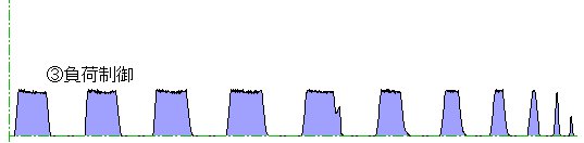
Cutting load rises rapidly at first, keep const, and at end decrease rapidly. The shapes are repeated.
This shape is a feature of Adaptive clearing.
In the above second animation of tool moved, overstep at corner is smaller, isn't it?
The Right of the garph corresponds to it.
The shape is narrow and as high as other terraces.
Empty areas without color blue mean air cut.
This Adaptive clearing has air cut more than other operations, but it is more efficient cutting than others.
The graphs of ① ② ③ has about the same X length adjusted by oversteps, and has the same Y-scale.
I put three graphs in one image.
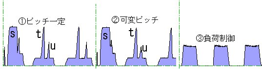
The three have the same blue areas that mean removed stock.
Why does Adaptive Clearing reduce roughing time?
Why does Adaptive Clearing increasing tool life?
Have you got answers?
I suppose cutting load is stock voluem removed per unit move which is Y-axis.
But in fact machining, it is influenced by deflection of tool and remaining chips and so on.
Back to square one
Let's go back to square one.What Z-depth?
When you use Apdaptive Clearing, it is OK maybe.
We are not liable for any machining. You must be liable for selecting parameters and machining.
I use images got from HSMWorks, add text and lines to some of them. I do not use video capture, but make animated GIF of static screen captures. And I use images made by other software.

 This html is made by MaaS Japan.